This page is intended for supplemental Mortty v5 information, or unique configurations that some Mortty owners may find helpful.
Send CW Sidetone to External Speakers
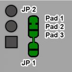
Mortty’s developers included solder pads on the I/O board to route the CW Sidetone to external speakers. As manufactured, Pads 1 and 2 of JP2 on the I/O Board are bridged, sending the RP2040 PWM (Pulse Width Modulated) digital audio to the Sidetone Board. The Sidetone Board contains a three-stage filter and amplifer to smooth those pulses into a sinewave for the internal speaker. If you want to process and amplify the CW sidetone with external speakers, add a solder bridge between JP2 Pads 2 and 3 and connect your external circuit to Ring2 of the CW Paddle jack..
To create a nice sinewave for your external amplifier & speakers, add a .1ufd capacitor to ground on the AUX I/O line. There is already a 1kOhm resistor in series from the RP2040 (as protection for the microcontroller), and the added .1ufd capacitor plus the 1kOhm resistor provide a nice smoothing filter with a high frequency rolloff at 1591Hz.
Use Mortty’s AUX I/O Feature
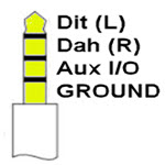
By default. Mortty’s front panel Paddle jack uses its Tip and Ring1 contacts for Dit and Dah signalling from a CW paddle. However, that jack includes a third conductor, Ring2, that can be re-purposed for an auxilliary function. Mortty’s developers included a solder pad on the I/O Board for passing a signal in-or-out of Mortty without drilling holes in the case or performing circuit board surgery. They also extended four unassigned RP2040 GPIO pins, GPIO 8-11, onto solder points on the CPU board. Exploiting these features in Mortty v5 requires serious expertise, but provides a customization capability not find elsewhere.