
Mortty v5 keyers are shipped assembled and tested, with no requirement for any Mortty software installation. Installing Mortty in your shack is a hardware exercise – specifically connecting Mortty to your computer, connecting Mortty to your CW Paddles, and building/buying the cables to connect Mortty to your transceiver.
Install
Mortty has three 3.5mm TRRS (Tip, Ring1, Ring2, Sleeve) jacks: two rear panel output jacks for Radio 1 and Radio 2, and one front panel input jack for CW Paddles and an AUX I/O function.
Connect Mortty to Your Computer
Using the USB cable provided in the Mortty package, connect Mortty to one of your computer’s USB ports. Windows should automatically recognize the new device and install the appropriate serial port driver. Successful installation will be announced with the familiar Windows tone and a brief text notice near the status bar of the PC. Open the Windows Device Manager dialog window by right-clicking on the Windows Start icon and selecting Device Manager.
In Device Manager, examine the Ports (COM & LPT) section for the new serial port. Note the serial port number assigned by Windows. You will need this number when configuring your logging software. If you can’t tell which port refers to Morrty, unplug Mortty’s USB cable while watching the Ports list – the one that disappears is Mortty!
Connect Mortty to Your CW Paddles
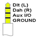
Mortty’s CW Paddle Input Jack
The front panel Paddle input jack connects: Tip = Dit (left paddle), Ring1 = Dah (right paddle), Ring2 = AUX I/O, and Sleeve = the USB-C port’s chassis ground. AUX I/O (ring2) connects to a solder pad on Mortty’s IO Board and can be used for – among other things – routing the CW sidetone audio to external amplified speakers.
Connect Mortty to Your Transceiver
Mortty has two rear panel 3.5mm TRRS (Tip, Ring1, Ring2, Sleeve) jacks for Radio 1 and Radio 2.
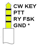
Mortty’s Radio 1 and Radio 2 Output Jacks
The rear panel output jacks for Radios 1 & 2 are identical: Tip = CW key, Ring1 = Push To Talk, Ring2 = RTTY FSK, and Sleeve = “GND*” Floating ground. The floating grounds isolate the radios’ grounds from each other, and isolate both outputs from the USB-C port’s chassis ground.
Decide Which Cable You Need
Mortty v5 can accommodate four cable configurations, ranging from simple (for CW) to not-so-simple (for CW and RTTY with PTT). If you can’t decide which cable you need, choose Cable D – which does everything. Also, if you plan to operate SO2R (Single Operator, 2 Radios) you will need two cables – one for each radio.
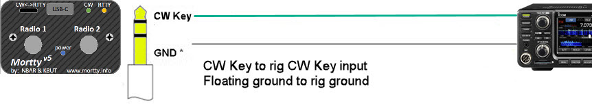
Mortty Cable A: Simple CW, no PTT
Hams who only intend to use Mortty’s CW mode, or who operate CW QSK, and do not require an independent push-to-talk line for controlling station peripherals, can use a simple stereo headphone cable, terminated with a male 3.5mm plug – a Tip Sleeve (TS) or a Tip Ring Sleeve (TRS) connector – on both ends. These cables are available off-the-shelf at electronics stores and on-line retailers. In both SO1R and SO2V configurations, Mortty keys the rig from the rear-panel Radio1 jack’s Tip connector.
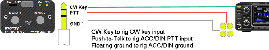
Mortty Cable B: CW with PTT
Most hams will want to use Mortty’s push-to-talk output to place their rigs in Tx and remain key-down until the end of their transmission. This requires extending the TRS jack’s PTT line to the rig ACC/DIN PTT input. Exactly which DIN plug you need depends upon the make/model of your transceiver.
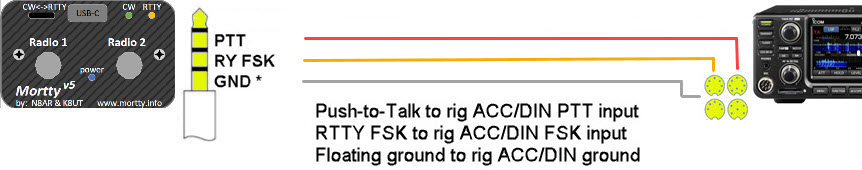
Mortty Cable C: RTTY with PTT
Operating RTTY FSK requires two signals, the push-to-talk line placing the rig in Tx, and the RTTY FSK line toggling the VFO between Mark and Space. Both of these rig inputs are only available on the rig ACC/DIN connnector. Exactly which DIN plug you need depends upon the make/model of your transceiver.
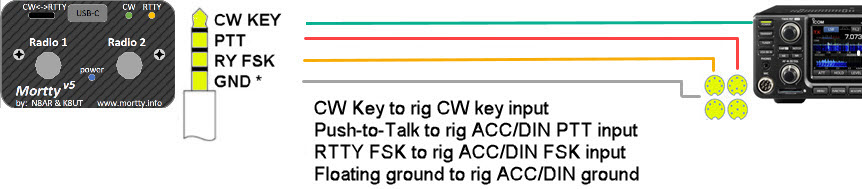
Mortty Cable D: CW and RTTY with PTT
Hams who anticipate using both of Mortty’s mode – CW and RTTY – can build/buy a single cable that will serve both purposes. Exactly which DIN plug you need depends upon the make/model of your transceiver.
Configure
For CW Keyer Mode
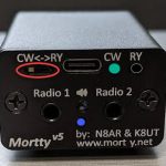
– If Mortty’s rear-panel CW (green) LED is not lit, check that Mortty’s rear-panel CW<->RTTY switch is in the CW (left side) position. Unplug and re-plug the USB cable into Mortty. The rear-panel CW (green) LED should light within one second of applying power.
– K3NG’s CW Keyer sketch emulates version 23 (v23) of the popular K1EL Winkeyer, which is supported by most {all?} logging programs. Follow your logging program’s instructions for configuring and using a Winkeyer.
– Mortty responds to changes you make in your logging program’s Winkey configuration (sidetone, sidetone frequency, PTT, lead time, tail time, keying mode, Use speed pot…).
– For N1MM SO2R operation, Mortty switches between Radio 1 and Radio 2 when the >Winkey 2/3 “Use 2nd Output” option is checked.
For RTTY TinyFSK Mode
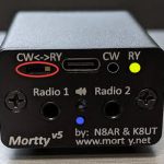
– If Mortty’s rear-panel RTTY (yellow) LED is not lit, check that Mortty’s rear-panel CW<->RTTY switch is in the RTTY ( right side) position. Unplug and re-plug the USB cable into Mortty. The rear-panel RTTY (yellow) LED should light within one second of applying power.
– Mortty v5 runs the latest version of K3NG’s CW Keyer sketch, which includes the code for running K0SM’s TinyFSK sketch. TinyFSK sketch is supported by many logging programs and digital mode applications. The list includes (at least) WriteLog, N1MM Logger Plus, Logger32, DXLab WinWarbler, G3YYD’s 2Tone, MMTTY… and probably others. Refer to your logging software’s documentation for TinyFSK interface instructions.
– Mortty responds to changes you make in your logging program’s Digital/RTTY configuration (RTTY baud rate, polarity [normal/reverse]).
– No contest logger supports Mortty’s SO2R enhancement in TinyFSK. If/when that changes an announcement will be made on the groups.io reflector.